
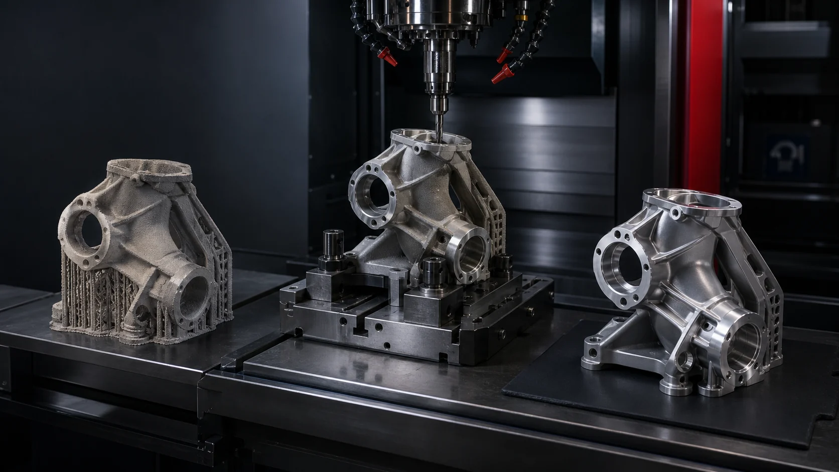
The printer produces a shape. The purchase order calls for a finished part.
That gap explains why metal additive manufacturing projects often become difficult after a successful build. Critical surfaces may still need machining. Supports and excess stock have to come off. Surface condition, cleaning, inspection, coating, and assembly requirements remain. If nobody planned those operations before printing, the near-net-shape part can arrive at the next supplier with poor datum access, too little machining allowance, or geometry that can’t be held safely.
A March 2026 strategy document developed through NASA, NIST, FAA, and industry participation says advances in additive manufacturing have not yet produced significant market penetration of AM parts in aviation. It identifies qualification and certification cost, long development timelines, and complex design iteration as major barriers. The report focuses on computational methods, but its larger message applies to sourcing: the process needs to be planned and supported with evidence.
The Print Is One Step in a Longer Route
NASA’s published process training for metal additive manufacturing shows a post-build route that can include powder removal, stress relief or other thermal processing, build-plate and support removal, inspection, final machining, polishing, and cleaning. The exact sequence depends on the material, printing process, design authority, service conditions, and governing specification.
No universal checklist can replace the engineering plan. A cosmetic prototype and a flight-critical component do not need the same controls. Still, buyers should define the finished condition rather than treating the print as the final manufacturing operation.
The 2026 CM4QC strategy document addresses the qualification problem in detail. NASA also provides a metal additive manufacturing process overview that maps common post-processing and inspection steps.
Plan Machining Before the Build
Machining an additive part differs from machining ordinary bar, plate, or a stable forging. The starting geometry may include supports, a build plate, sacrificial features, near-net surfaces, and internal passages. Part orientation during printing affects what the machinist receives.
The engineering package should identify which surfaces require final machining, the stock allowance available, the datums that establish part geometry, and how the workpiece can be held without distortion. It should also state whether support removal happens before or after thermal processing and who owns that operation.
Leaving “machine as required” on the drawing pushes unresolved design work into production. Sometimes the remaining stock won’t clean up. Sometimes the chosen datum disappeared with the support structure. Those are expensive discoveries after a long build.
Surface Finish Must Be Specified by Function
As-built additive surfaces can differ by process, orientation, material, and location on the part. Some surfaces may remain as built; sealing faces, bearing fits, threaded features, electrical contact areas, or fatigue-sensitive zones may need controlled finishing.
Define the required surface condition and measurement method on the drawing or process specification. If the part also needs blasting, polishing, chemical treatment, anodizing, passivation, paint, dry-film application, or another finish, identify which surfaces receive it and which need masking.
CMF’s metal finishing capabilities cover a broad range of treatments for metallic parts, subject to material compatibility, specification review, customer approvals, and CMF’s current process scope. Additive origin does not remove those checks.
Inspection Has to Follow the Process State
Inspection data only makes sense when the part’s condition is clear. A dimensional report taken before stress relief, final machining, or coating may not describe the delivered geometry. Likewise, removing stock can expose material that was not visible at the as-built stage.
Set inspection gates around the real risks. That may mean checking the raw build, verifying geometry after thermal processing, inspecting machined characteristics, and confirming the finished condition after coating or assembly. The engineering authority should decide which examinations and acceptance criteria apply.
The FAA and EASA continue to hold joint workshops on qualification and certification of additive aviation parts because process control and evidence remain active technical issues. The FAA additive manufacturing workshop page provides current background and proceedings.
Assign One Owner to the Full Manufacturing Route
An additive project can involve the print source, thermal processor, machine shop, finishing facility, inspection provider, and assembler. Splitting the work is sometimes necessary. Splitting responsibility is not.
The purchase package should state who controls revisions, approves source changes, maintains lot traceability, resolves nonconformances, and assembles the final certification package. It should also define how the printed serial or lot identity survives support removal and subsequent processing.
For parts that fit its equipment and approved process scope, CMF can support precision machining, finishing, and assembly after the additive build. CMF does not need to be the print source to review the downstream route, but the review works best before the build orientation and stock allowances become fixed.
Put These Questions in the RFQ
Ask for the supplied condition of the printed part, including material, build process, thermal history, support-removal state, and available certifications. Mark final datums, machined surfaces, tolerances, coating limits, masking areas, cleanliness requirements, and inspection responsibility. Then identify the governing specification and design authority.
That information lets a downstream manufacturer quote the real job. A CAD model by itself rarely does.
If you’re planning a metal additive component that will need final machining, surface treatment, or assembly, involve CMF before printing. An early manufacturing review can identify access, workholding, masking, and process-sequence issues while the design still has room to change.
Contact CMF to review the downstream manufacturing plan for your part.
This article provides general manufacturing information. The design authority, applicable specifications, approved process plan, and certification basis control each aerospace component.